1. Introduction to Compression Moulding
Compression moulding is a widely used manufacturing process in which a preheated polymer material (usually thermosetting plastic or rubber) is placed into a heated mould cavity. The mould is then closed, and pressure is applied to force the material to conform to the shape of the cavity. Heat and pressure are maintained until the material cures or sets into the final shape.
This process is commonly used to manufacture medium to large-sized parts, including automotive components, electrical housings, cookware handles, and more.
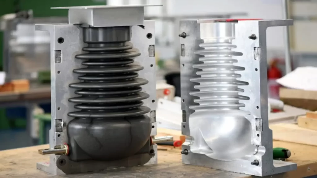
2. Components of a Compression Mould
A compression mould is made up of several key components that work together to form the desired shape of the product. These components include:
a. Cavity
The hollow part of the mould that defines the external shape of the final product.
Can be single or multi-cavity, depending on the number of parts to be produced per cycle.
b. Core
The male part of the mould that defines internal features or contours of the part.
Together with the cavity, it forms the complete mould impression.
c. Top and Bottom Platen
These are the plates of the compression press between which the mould is placed.
The top platen usually applies pressure, while the bottom remains stationary.
d. Guide Pins and Bushes
Used for aligning the top and bottom halves of the mould precisely.
Ensures that the core and cavity align correctly during mould closure.
e. Heating Elements
Moulds are equipped with heating systems (electric, steam, or oil) to maintain the curing temperature.
Thermocouples may be embedded to monitor temperature.
f. Ejector System (if required)
Some compression moulds have ejector pins or plates to remove the part after curing.
In many cases, the part is manually removed.
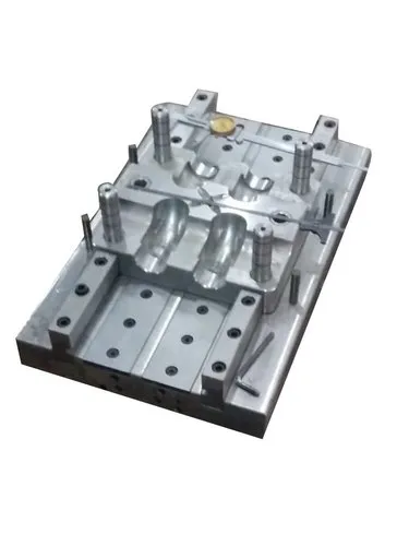
3. Base Construction of Compression Moulds
The base construction of a compression mould refers to the design and arrangement of the plates and supporting structures that hold the core and cavity inserts.
A typical mould base consists of the following:
a. Top Clamping Plate
Mounted to the upper platen of the press.
Holds the upper half of the mould in place.
b. Cavity Plate
Contains the cavity impression.
Fixed to the top or bottom half depending on design.
c. Core Plate
Contains the core impression.
Usually opposite the cavity plate.
d. Bottom Clamping Plate
Attached to the lower platen of the press.
Holds the lower mould half securely.
e. Spacer Blocks (if applicable)
Used to create space between clamping plates and core/cavity plates.
Facilitate installation of ejector systems or heating channels.
f. Ejector Box/Plate (optional)
When automated ejection is used, this component pushes the part out of the mould after curing.
Attached beneath the core side.
g. Locating Ring or Guide Bushings
Ensures alignment between top and bottom halves during mould closure.
Crucial for accurate and consistent part production.
4. Materials Used for Compression Mould Bases
The materials used in mould base construction must withstand high pressure and temperature. Common materials include:
Tool steels (e.g., P20, H13): High wear resistance and toughness.
Alloy steels: Good for large, less complex moulds.
Aluminum (for low-volume or prototype moulds): Lightweight, faster heating, but lower durability.
5. Types of Compression Moulds
Depending on the part design and production requirement, compression moulds may vary in construction:
a. Flash Type Mould
Excess material (flash) flows out at the parting line.
Simple and easy to design.
b. Positive Type Mould
The amount of material loaded is tightly controlled.
Little to no flash is produced.
c. Semi-Positive Mould
A hybrid between flash and positive type.
Offers better dimensional control than flash type but is easier to fill than positive type.
6. Design Considerations
Uniform Heating: Ensures consistent curing and part quality.
Ventilation: Allows gases to escape during compression.
Pressure Distribution: Proper design avoids warping or incomplete filling.
Ease of Ejection: Critical for minimizing cycle time and part damage.
7. Advantages of Compression Moulding
Ideal for high-strength, complex parts.
Low material wastage (especially with proper mould design).
Suitable for both small and large production runs.
8. Applications of Compression Moulds
Electrical components (switches, insulators)
Automotive parts (brake pads, bumpers)
Kitchenware (handles, knobs)
Aerospace and industrial components using composite materials
Conclusion
Compression moulds are critical tools in the manufacturing industry, enabling the efficient production of durable and complex parts. The construction of the mould base plays a vital role in ensuring accuracy, repeatability, and product quality. A well-designed mould base not only supports proper material flow and curing but also enhances operational lifespan and ease of maintenance.