The ejection system in a plastic injection mould is responsible for removing the molded part from the mould cavity after it has solidified. A properly designed ejection system ensures smooth part removal without damaging the part or the mould. It directly affects the cycle time, product quality, and mould life.
Objectives of the Ejection System
To release the molded part without deformation or damage.
To maintain dimensional accuracy of the part.
To ensure uniform ejection to avoid warping or stress marks.
To reduce cycle time through efficient ejection.
To avoid excessive wear and tear on mould components.
Components of an Ejection System
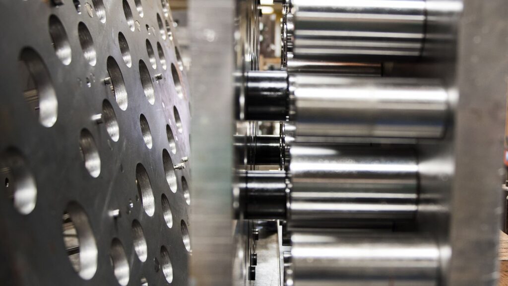
Ejector Pins
Most common method.
Push the part out by applying pressure from the core side.
Available in various shapes: round, flat, blade, sleeve pins.
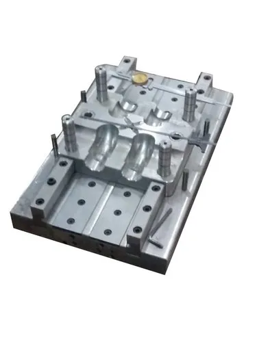
Ejector Plate (Ejector Assembly)
A moving plate that supports and drives all ejector pins.
Activated by ejector rods from the injection machine.
Return Pins / Ejector Return Springs
Help return the ejector system to its original position after ejection.
Guide Pillars and Bushings
Ensure smooth and aligned movement of ejector plates.
Back Plate / Support Plate
Provides structural support to the ejector assembly.
Lifters
Used for ejecting parts with undercuts.
Move at an angle to push the part out.
Sleeve Ejectors
Used for cylindrical parts like tubes.
Surround the core and push the part from all sides.
Stripping Plates / Collar Ejectors
Flat plates that eject parts with complex or delicate geometry.
Types of Ejection Methods
Pin Ejection
Simple and widely used.
Suitable for flat or block-shaped parts.
Blade Ejection
For thin-walled parts and areas where pin ejection may leave marks.
Sleeve Ejection
For hollow cylindrical parts.
Stripper Plate Ejection
For delicate parts with large surface areas.
Air Ejection
Uses compressed air to release the part.
Useful for fragile or light parts.
Lifter Ejection
Required when parts have side undercuts.
Provides angled movement to release the part.
Rotating Core Ejection
For threaded parts or complex undercuts.
Core rotates during ejection to unscrew the part.
Design Considerations
Part Geometry
Affects the choice of ejection method and pin placement.
Fragile features or thin walls need careful handling.
Material Shrinkage
Thermoplastics shrink as they cool, often adhering to the core side.
Ejection must compensate for this adhesion.
Ejection Force
Must be calculated based on part surface area, shrinkage, and material type.
Over-ejection can damage the part or mould.
Ejector Pin Placement
Must be balanced to avoid distortion.
Should be placed in thick sections to avoid marks.
Surface Finish
Highly polished surfaces are more prone to sticking.
Requires stronger or assisted ejection (air or sleeves).
Ejection Stroke
The distance the part needs to be pushed out.
Must clear the mould cavity completely.
Common Problems and Solutions
| Problem | Cause | Solution |
|---|---|---|
| Part sticking | Insufficient draft or ejection force | Increase draft angle or use air assist |
| Ejector pin marks | Improper pin location or excessive force | Optimize pin placement, reduce force |
| Warping on ejection | Uneven force or cooling | Use uniform ejection system, improve cooling |
| Part damage | Sharp edges or fragile areas | Use stripper plates or blade ejectors |
| Ejector pin wear | Poor alignment or hard material | Use guide elements and wear-resistant pins |